
Transfer Functions
The single complex-valued function that tells you everything a linear circuit does to a sinusoid — at any frequency.
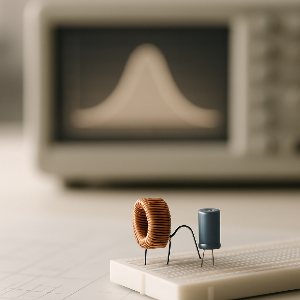
Your phone's speaker plays a bass drum and a piccolo at the same volume — but the tiny amplifier inside treats them very differently. Why?
What a transfer function captures
When you feed a sinusoidal input Vin(jω) into a linear circuit at angular frequency ω, the steady-state output Vout(jω) is another sinusoid at the same frequency — but generally with a different amplitude and a shifted phase. The ratio of output to input is the transfer function:
H(jω) = Vout(jω) / Vin(jω)
Because phasor voltages are complex numbers, H(jω) is complex-valued. Its magnitude |H(jω)| is the gain (amplitude scaling) at that frequency, and its argument ∠H(jω) is the phase shift the circuit imposes. Together these two real-valued functions of ω constitute the circuit's frequency response.
Deriving the RC low-pass transfer function
Consider a series resistor R and capacitor C driven by Vin across the pair, with Vout measured across the capacitor. In the phasor domain the capacitor's impedance is Z_C = 1/(jωC), so this is simply a voltage divider:
H(jω) = Z_C / (R + Z_C) = (1/(jωC)) / (R + 1/(jωC))
Multiplying numerator and denominator by jωC gives the clean form H(jω) = 1 / (1 + jωRC). Defining the corner frequency ωc = 1/(RC) lets us write the transfer function in normalized form as 1/(1 + jω/ωc), which separates the circuit's behavior from its specific component values.
Magnitude and phase at key frequencies
The magnitude and phase of H(jω) = 1/(1 + jω/ωc) are obtained by taking the modulus and argument of the denominator:
|H(jω)| = 1/√(1 + (ω/ωc)²) and ∠H(jω) = −arctan(ω/ωc)
Three regimes tell the whole story. At low frequencies (ω ≪ ωc), the filter passes the signal with unity gain and negligible phase shift. At the corner (ω = ωc), the gain drops to 1/√2 ≈ 0.707 and the phase is −45°. At high frequencies (ω ≫ ωc), the gain falls off as 1/ω and the phase approaches −90°. This is why it is called a low-pass filter: low frequencies pass through, high frequencies are attenuated.
- Compute RC = 1000 × 1×10⁻⁶ = 10⁻³ s, so ωc = 1/(RC) = 1/10⁻³ = 1000 rad/s.
- (a) At ω = ωc = 1000 rad/s: |H| = 1/√(1+1²) = 1/√2 ≈ 0.7071, and ∠H = −arctan(1) = −45°.
- (b) At ω = 3ωc = 3000 rad/s: |H| = 1/√(1+3²) = 1/√10 ≈ 0.3162, and ∠H = −arctan(3) ≈ −71.57°.
- Check limits: as ω → 0, H → 1 (0° phase); as ω → ∞, H → 0 (−90° phase). Consistent with low-pass behavior.
- RC = 500 × 1×10⁻⁶ = 5×10⁻⁴ s.
- ωc = 1/(RC) = 1/(5×10⁻⁴) = 2000 rad/s.
Check your understanding
- The transfer function H(jω) = Vout/Vin is a complex ratio whose magnitude gives gain and whose angle gives phase shift at each frequency.
- An RC low-pass filter has H(jω) = 1/(1 + jω/ωc) with corner frequency ωc = 1/(RC).
- At ω = ωc, the gain is 1/√2 ≈ 0.707 (the half-power point) and the phase is −45°.
- As ω → 0 the filter passes signals unaltered; as ω → ∞ it attenuates them toward zero with phase approaching −90°.