
RL Natural Response
The inductor's version of exponential decay — same mathematics, same time constant concept, but with a dangerous twist when the current path is suddenly broken.
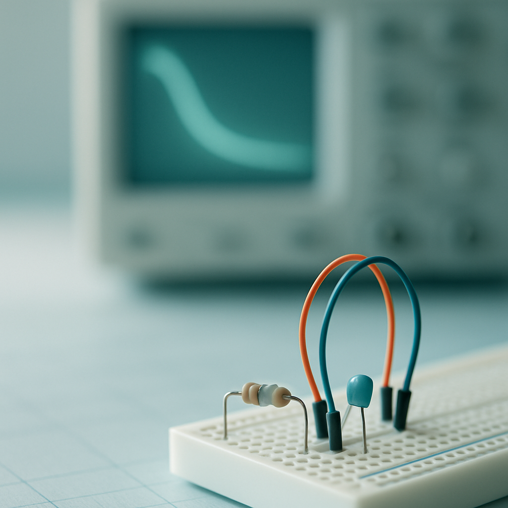
An inductor carrying current is like a flywheel — it resists any change in flow. Cut the circuit open and it will generate whatever voltage it takes to keep that current moving, even if that means arcing through the air.
The source-free RL circuit
Picture an inductor L carrying an initial current I0 — perhaps it was energized by a source that has just been removed, leaving only the inductor and a resistor R in a closed loop. This is the source-free RL circuit, and like its RC counterpart, it exhibits a natural response driven entirely by stored energy.
The inductor's current cannot change instantaneously, so at t = 0 the current is still I0. But the resistor dissipates energy, and as energy leaves the inductor's magnetic field, the current decays. Once again the shape is exponential.
Deriving the differential equation
We apply Kirchhoff's Voltage Law around the loop. The inductor voltage is L·di/dt and the resistor voltage is iR. With no source in the loop, their sum must be zero:
Solving for i(t)
The ODE has the same form as the RC case — a homogeneous first-order linear equation. Separating variables and integrating with the initial condition i(0) = I0 gives the solution:
The time constant τ = L/R
The ratio L/R has units of seconds (H / Ω = s) and serves as the time constant, τ = L/R. Just as in the RC case, at t = τ the current has decayed to e⁻¹ ≈ 36.8% of its initial value. The 5τ rule applies identically: after five time constants, the transient is practically over (less than 1% remaining).
Duality with the RC circuit
If you studied the Duality lesson in Module 5, this should feel familiar. The RC and RL natural responses are duals of each other — the same mathematical structure with quantities swapped:
RC: variable is voltage v, time constant τ = RC, ODE is dv/dt + v/(RC) = 0.
RL: variable is current i, time constant τ = L/R, ODE is di/dt + (R/L)i = 0.
The duality mapping is: C ↔ L, R ↔ 1/R (conductance), v ↔ i. Every result we derived for the RC circuit — the exponential form, the 1/e point, the 5τ rule, the energy balance — carries over directly with these substitutions. This is not coincidence; it reflects a deep structural symmetry in circuit theory.
Inductive kick: why interrupting an inductor is dangerous
Here is where the RL circuit departs from its gentle RC dual. The inductor's voltage is v = L·di/dt. If you try to instantly open a switch in an inductive circuit, you are demanding di/dt → ∞ in zero time. The inductor responds by generating an arbitrarily large voltage to keep the current flowing — even if that means ionizing air across the opening switch contacts (arcing) or destroying a transistor.
This is the inductive kick, and it is why relay coils, motor windings, and switching converters all use flyback diodes (also called freewheeling diodes). A diode is placed anti-parallel to the inductor: reverse-biased during normal operation, but when the switch opens and the inductor's voltage polarity reverses, the diode becomes forward-biased and provides a safe circulating path for the current. The energy then dissipates gradually through the diode and coil resistance instead of appearing as a destructive voltage spike.
Energy dissipation
The inductor starts with magnetic energy W = ½LI0². Just as the capacitor's energy was entirely dissipated in its resistor, all of the inductor's stored energy is converted to heat in R during the decay:
- Compute τ = L/R = 2 H / 10 Ω = 0.2 s.
- Write i(t) = I0 · e^(-t/τ) = 5 · e^(-t/0.2) = 5 · e^(-5t) A.
- Set i(t) = 1 A and solve for t: 1 = 5 · e^(-t/0.2), so e^(-t/0.2) = 0.2.
- Take the natural log: -t/0.2 = ln(0.2) = -1.609, giving t = 0.2 × 1.609 ≈ 0.322 s.
- As a check, the initial energy stored is ½LI0² = ½(2)(5²) = 25 J, all dissipated in the resistor.
- Compute τ = L/R = 5 H / 10 Ω = 0.5 s.
- Evaluate i(t) = 4 · e^(-t/0.5) at t = 0.5: i(0.5) = 4 · e^(-0.5/0.5) = 4 · e^(-1).
- e^(-1) ≈ 0.3679, so i(0.5) ≈ 4 × 0.3679 ≈ 1.47 A.
Check your understanding
- A source-free RL circuit contains no independent sources — only an inductor (initially carrying current I0) and a resistor in a closed loop.
- Applying KVL yields the first-order ODE di/dt + (R/L)i = 0, whose solution is i(t) = I0·e^(-Rt/L).
- The time constant τ = L/R (in seconds) governs the decay rate; at t = τ the current has fallen to ≈36.8% of I0.
- The RL natural response is the exact dual of the RC natural response: C ↔ L, v ↔ i, R ↔ 1/R.
- Interrupting an inductor's current path causes a dangerous voltage spike (inductive kick); flyback diodes provide a safe discharge path.
- All initial energy ½LI0² stored in the inductor is dissipated as heat in the resistor.