
The Hull Girder as a Beam
Treat the whole ship as one long, hollow box girder floating freely in the water, and the entire machinery of beam bending — shear force and bending moment — applies to it directly.
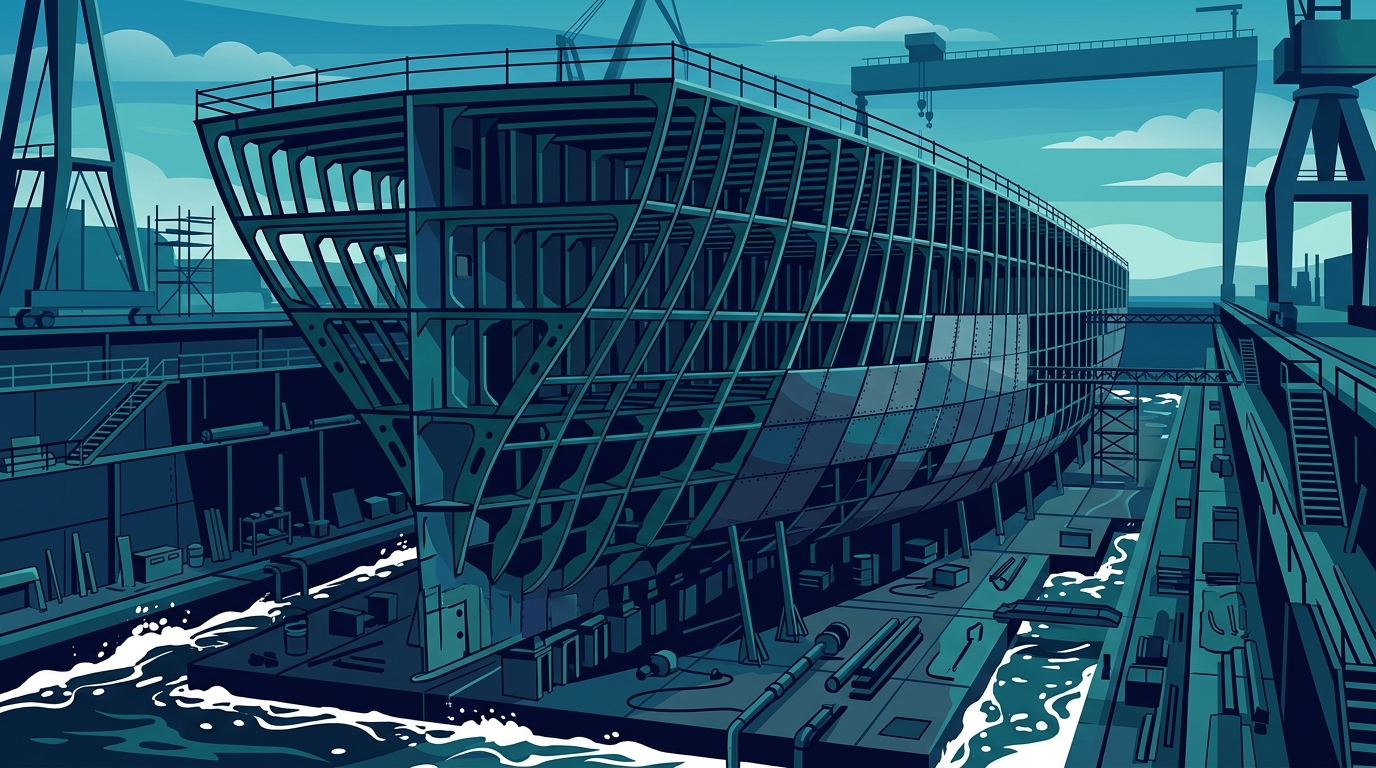
A 200-metre ship looks nothing like a lab specimen — but to a structural engineer it is just a very long, very hollow beam, floating freely in the water and bending under the mismatch between its weight and its buoyancy.
The Whole Ship as One Beam
A ship's deck plating, bottom plating, side shell, longitudinal bulkheads, and internal structure are not independent parts — they act together as a single long hollow tube called the hull girder (or box girder). When you stand back far enough, every ship is just a very large beam floating in the water, and the beam-bending theory you met in the Solid Mechanics course applies to it almost unchanged.
The one feature that makes a ship unlike a bridge or a roof beam is its support. A ship is a free-free beam: it is not pinned or held up at its ends. Instead it is supported everywhere at once by the distributed upward pressure of the water (buoyancy), and loaded everywhere at once by its distributed downward weight. At any cross-section along the length the net load per unit length is the local weight minus the local buoyancy. Where weight exceeds buoyancy the section is pushed down; where buoyancy exceeds weight it is pushed up. It is precisely this varying net load that bends the hull girder.
From that net load the two internal actions follow directly, just as in any beam: the shear force at a section is the running integral of the net load up to that point, and the bending moment is the running integral of the shear force. The bending moment is the quantity that ultimately stresses the hull girder, and it is what the rest of this module is about.
Hogging Versus Sagging
The sign of the bending moment tells you which way the hull is bending, and naval architects use two everyday words for the two cases:
- Hogging — the hull bends so that the middle rises relative to the ends, like a hog's arched back. The deck is in tension and the bottom (keel) is in compression. Hogging occurs when buoyancy is concentrated amidships (a wave crest amidships) or when weight is concentrated toward the ends.
- Sagging — the hull bends so that the middle drops relative to the ends. The deck is in compression and the bottom is in tension. Sagging occurs when weight is concentrated amidships or when a wave trough sits amidships.
The distinction matters because steel behaves differently in tension and compression: tension governs fatigue cracking at details, while compression governs the buckling of slender deck plating. A hull girder must be designed to survive both hogging and sagging, because the same ship will experience each at different moments as waves pass underneath and as cargo distribution changes.
Because hogging puts the deck in tension and sagging puts it in compression, the two cases stress the hull in different ways and are checked separately. Compression can buckle slender deck plating between stiffeners; tension grows fatigue cracks at welded details. A hull girder that comfortably survives one case may still be vulnerable to the other — which is why both hogging and sagging moments are computed for every loading and wave condition.
- M = wL²/8 = 200 × 100²/8 = 200 × 10,000/8
- = 2,000,000/8 = 250,000 kN·m
- Converting to MN·m: 250,000 kN·m ÷ 1000 = 250 MN·m
- M = wL²/8 = 150 × 120²/8 = 150 × 14,400/8
- = 2,160,000/8 = 270,000 kN·m
- = 270,000 ÷ 1000 = 270 MN·m
Check your understanding
- The whole ship is a hull girder — a free-free beam supported by distributed buoyancy and loaded by distributed weight; the net load bends it
- Shear force is the running integral of net load, and bending moment is the running integral of shear force — the quantity that stresses the hull
- Hogging (midships rises, deck in tension) and sagging (midships drops, deck in compression) are the two cases every hull girder must survive