
Load Paths & the V-n Load Envelope

Sizing Structure to the Flight Envelope
Aerospace EngineeringStructures & MaterialsFree preview
⏱️ About 25 min
Load Paths & the V-n Load Envelope — illustration
Decorative illustration.

Every maneuver an aircraft executes translates into structural loads. The V-n diagram is the foundational map that guides aerospace engineers in sizing the airframe to survive both expected and extreme flight conditions.

💡
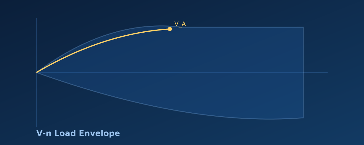
The big idea: The V-n diagram bounds the load factor \(n=L/W\) versus airspeed. The stall boundary intersects the structural limit to define the maneuvering speed \(V_A\), ensuring the aircraft stalls before exceeding its ultimate load.
🎯 By the end, you'll be able to
  • Interpret the axes and boundaries of a standard V-n maneuvering envelope.
  • Calculate the maneuvering speed \(V_A\) given the 1-g stall speed and limit load factor.
  • Determine the ultimate load by applying the standard 1.5 factor of safety to limit loads.
📎 Helpful to know first
  • Basic understanding of lift, weight, and aircraft stall speed.

The Flight Envelope

The V-n diagram plots the load factor, meaning \(n=L/W\) where lift is \(L\) and weight is \(W=mg\), against airspeed. This envelope defines the structural limits of the aircraft, ensuring it can safely withstand both steady and maneuvering flight loads.

Stall and Structural Limits

At low airspeeds, the aircraft reaches its stalling angle of attack before the structure reaches its limit. The stall boundary follows the relationship where load factor scales with the square of airspeed. The stall parabola meets the structural limit at the maneuvering speed \(V_A\).

\[ n = \dfrac{L}{W} \]

Maneuvering Speed

Maneuvering speed \(V_A\) is the maximum speed at which full, abrupt control deflections will not exceed the structural limit load. At this speed, the aircraft will stall exactly as it reaches the limit load factor \(n_{limit}\), protecting the airframe.

\[ V_A = V_s\sqrt{n_{limit}} \]
🔑 Ultimate Load Factor

Aircraft structures are designed with a safety margin. The ultimate load equals the limit load multiplied by a factor of safety, commonly 1.5. The structure is designed not to fail at the ultimate load, so expected flight loads stay well inside its strength.

🎮 V-n Load Envelope Explorer LIVE
Predict first: Adjust the 1-g stall speed and limit load factor to reshape the maneuvering envelope.
The stall parabola meets the structural limit at the maneuvering speed.
📝 Worked example: An aircraft has a 1-g stall speed \(V_s\) of 50 m/s and a structural limit load factor \(n_{limit}\) of 3.8. Calculate the maneuvering speed \(V_A\) and the ultimate load factor.
  1. 1. Calculate maneuvering speed: \(V_A = V_s\sqrt{n_{limit}} = 50\sqrt{3.8}\)
  2. 2. Compute the square root: \(50 \times 1.9494 = 97.47\) m/s
  3. 3. Calculate ultimate load factor: \(1.5 \times 3.8 = 5.7\)
✓ The maneuvering speed is about 97.47 m/s and the ultimate load factor is 5.7.
✏️ Practice: Given a 1-g stall speed \(V_s=40\) m/s and a limit load factor \(n_{limit}=4.4\), find the maneuvering speed \(V_A\).
Solution
  1. Hint: V_A=V_s*sqrt(n_limit).
  2. Answer: V_A = 83.9 m/s.

Check your understanding

1. The stall boundary of a V-n diagram varies with airspeed as:
Lift, and thus the achievable load factor before stall, is proportional to the square of airspeed.
2. The ultimate load equals the limit load times what factor of safety?
The standard aircraft structural factor of safety is 1.5.
✅ Key takeaways
  • The V-n diagram maps load factor against airspeed to define safe flight boundaries.
  • Maneuvering speed is where the stall boundary intersects the structural limit load.
  • Ultimate load is 1.5 times the limit load, providing a critical safety margin.
➡️ Now that we understand the external flight loads an aircraft must survive, we must look inside the airframe to see how those loads are physically carried. Next, we explore semimonocoque construction and the concept of shear flow.